There are three choices:
(i) Build Version One on this page. (small and awkward circuit board)
(ii) Build Version Two or Version Three (easier construction using Veroboard-style circuit board).
(iii) Buy the kit from the ATA (Melbourne, Australia)
Build this simple Mini Maximiser
Greatly improve the performance
of solar-powered pumps and motors
by building this
simple mini-maximiser.
by Alan Hutchinson, Plasmatronics, Melbourne (this Web version with his permission)
One of the more common uses of solar electric (photovoltaic) panels is driving motors and in particular for water pumping.
The motor is connected directly to the solar panels and no storage battery is used. This arrangement works well but suffers from one major weakness. Because solar panels are effectively constant current sources they cannot deliver extra power for starting like a battery can. In fact, due to the low resistance of motors when stopped, the panels can only deliver a small fraction of their normal power during start up. This means that there is very little power available at the time it is most needed to get the motor running. Fortunately, this problem can be easily solved by using an electronic device to match the panel to the motor so as to allow the panel to deliver its full power into the motor even when the motor is stalled. A variety of such devices are available on the market such the "Maximiser" and various forms of maximum power point trackers. These are quite sophisticated devices costing some hundreds of dollars. This is OK for a large pump setup but for a small one or two panel system it is a bit expensive. Here is a simple mini- maximiser that you can build yourself and will perform almost as well as some of the more expensive ones.
How it works
First let's take a closer look at the problem. The motor driven diaphram pump used here for testing the maximiser is a 12V motor nominally rated at 6amp. The pump would not start even when unloaded when driven from a single 50W panel (an Arco M55). With 3.3Amp from the panel flowing through the motor, 1.2 volt was measured across the motor. Hence the power going into the motor is only 1.2 x 3.3 = 4 Watt. If the panel was being operated at its peak power point (about 17.5V), it could have delivered 55W rather than the paltry 4W it actually delivered.
So the problem is that we need to get the panel to supply its energy at 17V but somehow we need to deliver it to the motor at a lower voltage. More expensive maximisers use switchmode down converters to perform this function of acting like a DC transformer. This maximiser is much simpler.
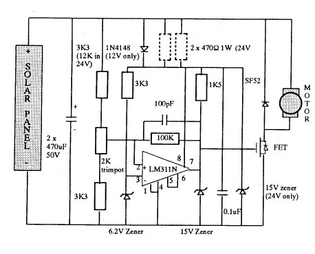
The circuit diagram shows that it is basically a large capacitor across the panel which can be connected by an electronic switch to the motor. When the switch is off, the capacitor will be charged up by the panel. As the open circuit voltage of the panel is usually above 20V, the capacitor can charge to quite a high voltage. When the capacitor voltage rises above an adjustable set point (in the range 10.5-17 volts) the electronic switch (the FET) turns on. This connects the motor across the capacitor and will draw a lot of current from the capacitor into the motor. This will cause the capacitor to discharge rapidly. When the capacitor voltage falls about half a volt below the set point, the FET will switch off again and allow the capacitor to charge up again. This cycle then repeats indefinitely. It is basically a free running oscillator with the rate of charge determined by the panel charge current and the rate of discharge determined by the amount by which the motor current exceeds the panel current. Yes, it is possible to get more current flowing into the motor than is coming out of the panel!)
So what have we got happening? The panel is delivering a steady 3 amp at close to the set point voltage. If the set point is set close to the maximum power point of the panel, the panel will be delivering as much power as it can. On the motor side, the motor will be driven with pulses of high current which is excellent for providing the high torque necessary to get it moving. When its stalled, the pulses will be large but of short duration. As the motor picks up speed, the voltage across it will rise due to the back EMF and the pulses will be at a lower current but of longer duration. This means that the frequency of the oscillator will fall as the motor gets going. In this example, the frequency when running was about 1Khz and the switch was off for about 1/3 of the time.
What it did
The improvement in performance due to the maximiser was amazing. Without it, the pump motor would not even run unloaded, even if it was turned over by hand. With the maximiser, it started up and ran well. With the set point voltage at 13V, the panel current measured 3.2A (input power 41W) and we had it pumping water up 6 metres.
Circuit details
The two large electrolytic capacitors are charged by the solar panel and then quickly discharged into the load by the FET switch.
A BUK455-60A is used. for the electronic switch. This will block 50V and has an on resistance of 0.03 Ohm. Because of the low on resistance it is not necessary to provide a heat sink. The SF52 is a very fast recovery diode (normal diodes are not good enough) that is used as a catch or freewheeling diode. This provides a path for the motor current to flow through when the switch is off. This protects the FET from high voltage spikes when it switches off.

Construction
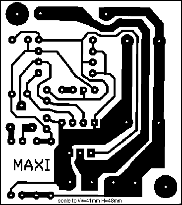
This is not a difficult device to make. It takes about 1 hour to put together. To make it easier, the circuit is constructed on a piece of predrilled circuit board supplied in the kit. The components are mounted on the opposite side from the copper tracks according to the layout diagram. Take care to get all the diodes,the LM311, the FET, and the large capacitors round the right way. Solder the components on, taking care not to create bridges between tracks.

